Cut Plans or Cut Projects
In the context of this glossary, the Cutting plan can be defined as a set of instructions or indications to guide the cutting of a material from which parts are to be taken. These plans contain practical and precise instructions to save time with a minimum of error, when cutting. These cut-specific guidelines can be sent directly to automated machines such as saws, shears or CNC cutting machines, with even greater productivity benefits.
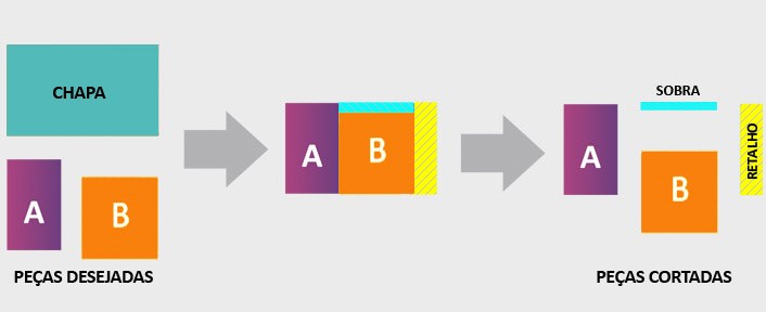
Although the word plan also contains the meanings of scheme, drawing, map, draft, etc… this information can be presented through lines of code. When they are supported by graphic representations, they may have more clarifying names such as cutting scheme, cutting map, diagram or layout. The images explain it better:
If it is to establish a relationship with planning, we can say that this is the phase in which the limitations to the calculation are determined, such as, if the shaft direction should be maintained, if there will be additional wear on the edges of the pieces after cutting. , if the thickness of the cutting instrument will consume part of the material, etc…
Naturally, there are simpler cutting plans and others of great complexity. More configured limitations, in general, imply greater complexity.
In cases of zero complexity, the plan does not even exist. An example is the glazier who cuts the glass he needs for a picture frame on any side of the plate. Or the carpenter who uses whatever is left over to replace a damaged piece. But there are cases of extreme simplicity that prevailed (and that still survive!) in the times that preceded software and that are legitimate cutting plans. How, for example, to cut a thousand rectangular pieces of different sizes? There was no other way: the cutting plan was being produced one by one, by hand, starting from the size of the plate and, generally, exhausting each quantity of a piece size, before starting to fit the other pieces. In the early days of software, this work could be automated for cutting machine operators, who began to use x-y coordinates to produce their cutting planes more quickly and with greater precision.
Nowadays, the cutting plans generated by Corte Certo start by anticipating more than precious information for the Budgets and Purchasing area: the number of sheets needed to fulfill the order. Going beyond the cutting process, it can indicate edge finishing, such as banding, in the furniture industry, or beadwork, in glass – among others.
Most common information present in a sheet metal cutting plan:
- Material to be cut
- Overview with all plan cutting schemes
- Number of repetitions of the same scheme
- Position and identification of each fitted part
- Dimensions of sheets and parts
- Scraps with dimensions
- Leftovers with dimensions
- Extra parts with dimensions
- Order of cuts
Main components of a cutting plan produced for sheet metal.
Corte Certo can be configured to show more on screen. Some examples:
- Different forms of description for parts or scraps.
- Marking of very small parts.
- Signaling the last piece of the same size in the project.
- Ribbons or trim on the edges.
- Indication of the texture direction in the pieces.
- Grouping of equal parts by the same color.
- Others
Complementary statistical reports further enrich the information. Examples:
- Weight of the pieces or each project (for freight calculation).
- Prices in different ways.
- Use (in various ways)
- Volume (m3)
- Perimeter
- Others
To get an idea of the refinement of this information: it is even possible to know, before cutting the material (wooden boards, in the example) how much sawdust will be generated!
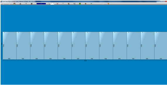
It should be noted that the number of cutting schemes is not always equivalent to the number of sheets. This is a very common confusion: the user counts 10 schemes in the Thumbnails Menu and thinks he will use 10 plates. Sometimes there is no such equivalence because Corte Certo tries to stack sheets, that is, to make more sheets be cut in the same way. In the Thumbnails Menu itself or in the printed cutting plan, among other places, there are clear indications of the number of plates that must be cut with that same design, as shown in the figure below.
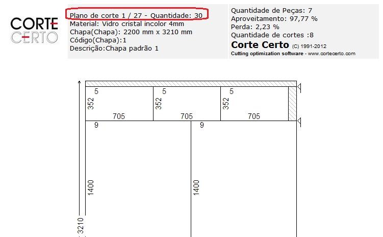
Cutting plane can refer to a unit of a set of plans (as in the example above: plan 1 of 27), but it can also refer to the whole set, that is, the entire project. To minimize this little confusion, there are those who prefer to use other names for these units, such as: cutting scheme, cutting map, diagram or layout.
The cutting plans can consider several materials, such as paper, cardboard, glass, wood, stainless steel, metallic compounds (ACM), acrylic, marble, granite, styrofoam, cork, foam, coatings in general, fabrics, leather, porcelain, aluminum, steel, etc. The materials can also be packaged in sheets, bars, coils, etc.
The two types of cut also apply to coils, which may optionally require planes for longitudinal cuts.
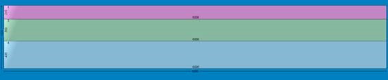
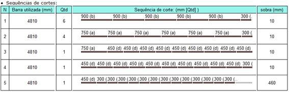
For linear materials, graphic planes are not always necessary, numerical references of the cut points are sufficient, as shown in the example below:
Bar used: 30 x 2144 mm
Cut sequence: 720 (1) (h) 720 (1) (h) 700 (1) (a)
Overhead: 4mm
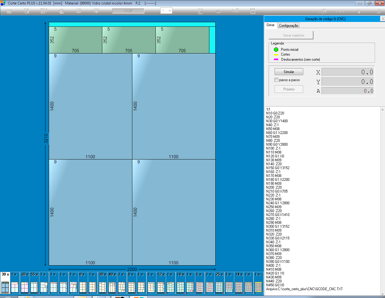
But the visual option also exists, as in the example made by Corte Certo: